T04E Carbon Seal Conversion Kit: Step-by-Step Installation Instructions
The T04E carbon seal kit installation is a job most people can do on a clean bench with ordinary hand tools. The carbon seal conversion replaces the factory piston-ring seal on the compressor side with a carbon face seal, which is what you want on a turbo that sees a lot of idle time or a draw-through setup where the old ring seal keeps weeping oil into the compressor housing.
This page is the complete procedure for the PT Turbo T04E Carbon Seal Conversion Kit, start to finish. Read it all the way through before you pick up a wrench. At PT Turbo we have been rebuilding turbochargers since 1978, and if you get stuck at any point we will finish the rebuild for you and credit the kit you already bought.
Fits: most journal-bearing T04E turbochargers. Does not fit: ball-bearing T04E models.
Download the printable PDF instructions
The PDF is the same procedure with photographs of every step, laid out to take to the bench. Everything below is the same content in text form.
Check Your Parts Before You Start
Check off every part before you take anything apart. Each number matches the exploded photo on page 1 of the PDF.
| # | Part | Qty | Used in |
|---|---|---|---|
| 1 | Billet seal plate (black anodized) | 1 | Steps 11, 17, 20 |
| 2 | Carbon seal (already installed in the seal plate, do not remove) | 1 | Step 11 |
| 3 | Spring ring | 1 | Step 11 |
| 4 | Journal bearings | 2 | Step 12 |
| 5 | Snap rings | 4 | Step 12 |
| 6 | Thrust collar, 2-piece (bottom half and top half) | 1 set | Steps 13, 15 |
| 7 | 360° thrust bearing | 1 | Step 14 |
| 8 | Bearing housing O-ring (the thin O-ring right around the spring ring) | 1 | Step 16 |
| 9 | Thrust spacer | 1 | Steps 18, 19 |
| 10 | Seal plate bolts | 4 | Step 20 |
| 11 | Stagger-gap turbine seal | 1 | Step 21 |
| 12 | Shaft nut | 1 | Step 24 |
| 13 | Compressor housing O-ring (the large O-ring) | 1 | Step 26 |
Tools and Supplies
- Paint marker or scribe for alignment marks
- Socket set and wrenches
- Snap ring pliers
- Torque wrench, to tighten to original spec
- Clean engine oil for assembly
- Parts cleaner and compressed air
- Clean, lint-free rags
- Your phone camera, to take pictures as you tear down
The Golden Rules
- Work clean. Dirt kills turbos. Clean bench, clean hands, clean rags.
- Mark it before you take it apart. Housings and wheels must go back exactly where they came from.
- Do the steps in order. Do not skip steps and do not combine them.
- Oil every part as it goes back together. Use clean engine oil.
- Never force anything. If a part will not go, stop. Something is not lined up.
- Use every new part in the kit. Do not reuse the old parts the kit replaces.
Part 1: Take It Apart
Work from the outside in, and take photos as you go.
1. Mark the housings. Before you loosen anything, draw a paint line across the compressor housing and the center section. Draw another across the turbine housing and the center section. This is so both housings go back at the exact same angle.
2. Remove the housings. Take off the compressor housing and the turbine housing.
3. Mark the wheels. Put a mark on the compressor wheel and a matching mark on the turbine wheel, lined up with each other. The compressor wheel must go back in the exact same spot to keep the turbo balanced.
4. Remove the shaft nut. Hold the turbine end still, never by the blades, and loosen the nut. Careful: some shafts have reverse (left-hand) threads. If the nut does not loosen easily counterclockwise, stop and do not force it. Try clockwise. Forcing it the wrong way can break the shaft.
5. Remove the compressor wheel. Slide the compressor wheel off the shaft.
6. Remove the shaft. Slide the shaft, with the turbine wheel on it, out through the turbine (exhaust) side.
7. Remove the backplate. Remove the bolts that hold the old backplate to the center section, then lift the backplate off.
8. Remove the thrust parts. Remove the thrust bearing, thrust collar and the other thrust parts. Take a photo first and lay the parts out in the order they came off.
9. Remove the journal bearings. Remove the snap rings that hold the journal bearings in, then pull both journal bearings out.
Your center section, shaft and turbine wheel, compressor wheel and both housings all go back on. Every other old part gets replaced by the kit.
Part 2: Clean and Inspect
10. Clean and inspect. Clean every part you are reusing until there is no oil, carbon or dirt left, and blow out every oil passage with compressed air.
Then inspect. Look at the wheels for any bent, chipped or rubbed blades. Look at the shaft for any scoring or wear where the bearings ride. Look at the housings for any rub marks or cracks.
If you find damage, stop. Do not put damaged parts back in. Call us at (909) 824-1020 before you go any further.
Part 3: Rebuild the Center Section
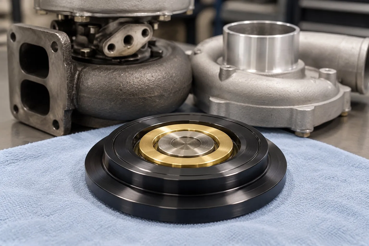
Do these steps in this exact order, one at a time. Coat each bearing and thrust part with clean engine oil, and lightly oil each O-ring. The shaft does not go in yet, that happens later in Step 22.
11. Check the seal plate. Look at the back side of your new seal plate, the side that faces the center section. The carbon seal comes already installed in the middle. Do not remove it. Make sure the spring ring sits flat in its pocket around the carbon seal, then set the plate aside on a clean rag. Check: the spring ring is flat and fully seated, and the carbon seal is clean, with no dirt and no scratches.
12. Install the journal bearings. Oil the 2 new journal bearings. Install each one with 2 of the new snap rings, in the same grooves the old ones came out of. Then set the center section down with the compressor side facing up. Find the 2 locating pins and the oil drain opening, you will need them in Step 14. Check: all 4 snap rings are fully snapped into their grooves, all the way around.
13. Bottom half of the thrust collar. Oil it. Drop it into the center hole with the big flange down and the tube pointing up. Check: it sits flat in the hole with the tube pointing straight up.
14. Install the thrust bearing. Oil both sides. Slide it down over the tube of the thrust collar. Turn it until the 2 locating pins from Step 12 drop into the matching holes in the thrust bearing. The cut-out notch must face the oil drain opening. Check: it sits dead flat, with no rocking. If it rocks, it is not on the pins.
15. Top half of the thrust collar. Oil it. Set it on top of the tube, centered, so it sits flat on the thrust bearing. The thrust bearing is now sandwiched between the two halves of the thrust collar. Check: the top half sits flat and centered.
16. Bearing housing O-ring. Lightly oil the new bearing housing O-ring and press it into the groove around the thrust bearing. Check: it is all the way down in the groove, all the way around, with no twists and nothing sticking out.
17. Turn the seal plate over. Take the seal plate from Step 11 and turn it over, so the compressor-wheel side faces up. That is the side with the stepped rings and no bolt holes. The gold ring in the center is the back side of the carbon seal. Check: you can see the gold ring, and the plate is lying flat on a clean surface.
18. Hold the thrust spacer this way. Oil it. Hold the thrust spacer with the flange up and the tube down. Important: it must go in from this side, the compressor-wheel side. Never install it from the back.
19. Push the thrust spacer in. Slide the tube down into the center of the gold ring. Push it in until the flange sits flat inside the gold ring. Check: the flange is flat, level and centered inside the gold ring. From now on, keep the plate compressor side up so the spacer cannot fall out.
Part 4: Put the Turbo Back Together
20. Mount the seal plate. Keep the seal plate compressor side up and lower it straight down onto the center section. Line up the 4 bolt holes. Do not let the O-ring get pinched or roll out of its groove. Install the 4 new seal plate bolts and tighten them a little at a time in a criss-cross pattern, to original spec. Check: the plate sits flat all the way around, and no O-ring is showing.
21. Install the turbine seal. Put the new stagger-gap turbine seal into its groove on the turbine end of the shaft, where the old one came off. Spread it only enough to slip it on. Do not bend it out of shape.
22. Slide the shaft in. Oil the shaft. Slide it in from the turbine (exhaust) side, through the journal bearings, the thrust collar and the thrust spacer. Gently ease the turbine seal into the bore. Never hammer or force it. Check: the turbine wheel is all the way in, and the shaft sticks out through the thrust spacer on the compressor side.
23. Put the compressor wheel on. Slide the compressor wheel onto the shaft. Line up the marks you made in Step 3 so the turbo stays balanced.
24. Tighten the shaft nut: snug plus a quarter turn. Thread the new shaft nut on by hand until it just touches the compressor wheel. Make a paint mark on the nut and a matching mark on the compressor wheel. Hold the turbine end still and turn the nut 90 degrees more, a quarter turn, then stop. This stretches the shaft the right amount. Do not go past a quarter turn. If you have a reverse-thread shaft, the nut tightens counterclockwise.
25. Spin test. Spin the shaft by hand. It must spin freely and smoothly, with no rubbing, grinding or tight spots. If it does not, stop and find out why before you go on.
26. Install the housings. Lightly oil the new compressor housing O-ring and fit it in its groove on the outer edge of the seal plate. Reinstall the turbine housing and compressor housing, lining up the marks from Step 1. Tighten to original spec. Final check: spin it again. The wheels must not touch the housings anywhere.
Part 5: Before the First Start-Up
Pre-oil the turbo. Before you hook up the oil feed line, pour clean oil into the turbo’s oil inlet while you slowly turn the shaft by hand.
Check the oil drain. The drain line must be clear, not kinked, and run downhill to the oil pan. A restricted drain can make any turbo leak oil, even one with carbon seals.
Idle and look. Start the engine and let it idle. Check for oil leaks at every fitting before you drive it or make boost.
Final Checklist
- Every kit part used, nothing left in the bag
- Thrust bearing notch faces the oil drain
- Thrust spacer went in from the compressor side
- Seal plate bolts tightened criss-cross to spec
- Compressor wheel marks lined up
- Shaft nut: snug plus a quarter turn, no more
- Shaft spins freely, no rubbing
- Housings back on their marks, tightened to spec
Stuck? We Will Finish It for You
If you get stuck at any point, or decide you would rather have us do it, send it to us. We will finish the rebuild, or start it over, and give you credit toward the rebuild price for the kit you already bought from us.
Call (909) 824-1020, Monday to Friday, 8 AM to 5 PM. We are at 346 S I St. STE #3, San Bernardino, CA 92410.
You can order the kit here: T04E Turbo Carbon Seal Conversion Kit with Billet Seal Plate, Bearings and Hardware.
Frequently Asked Questions
Will this kit fit a ball-bearing T04E?
No. The kit fits most journal-bearing T04E turbochargers only. Ball-bearing T04E models use a different cartridge and this seal plate will not work on them. If you are not sure which one you have, call us with your part number and we will check it for you.
Why does the shaft nut only get a quarter turn?
The shaft nut is torqued by stretch, not by a torque value. Threading it until it just touches the compressor wheel takes up the slack, and the extra 90 degrees stretches the shaft the correct amount to clamp the wheel without distorting it. Going past a quarter turn over-stretches the shaft and can cause it to fail in service.
Do carbon seals stop all oil leaks?
They stop leaks caused by a worn or poorly sealing compressor-side ring seal, which is the most common cause. They do not fix a leak caused by a restricted or kinked oil drain line, or by high crankcase pressure pushing oil past the seal. Check the drain before you blame the seal.
Prefer to leave it to a shop? PT Turbo’s turbo rebuild service includes carbon-seal conversions.
Need a Turbocharger?
PT Turbo has rebuilt and sold turbochargers since 1978. We stock remanufactured units for Cummins, Duramax, Power Stroke, Detroit Diesel, and more — backed by a 12-month unlimited mileage warranty. Units in stock at our shop in San Bernardino, CA ship the same day when ordered before 2 PM Pacific, Monday through Friday.
📞 (909) 824-1020 · 346 S I St. #3, San Bernardino, CA 92410 · [email protected]